BVOCDTA Disabled Toilet Alarm Kit Manual
The BVOCDTA Disabled Toilet Alarm Kit Manual provides detailed instructions for installing, configuring, and operating a disabled persons’ toilet alarm system, ensuring compliance with the BS8300:2009 standard. This system is designed to provide a reliable and easy-to-use emergency assistance alarm for disabled WC installations.
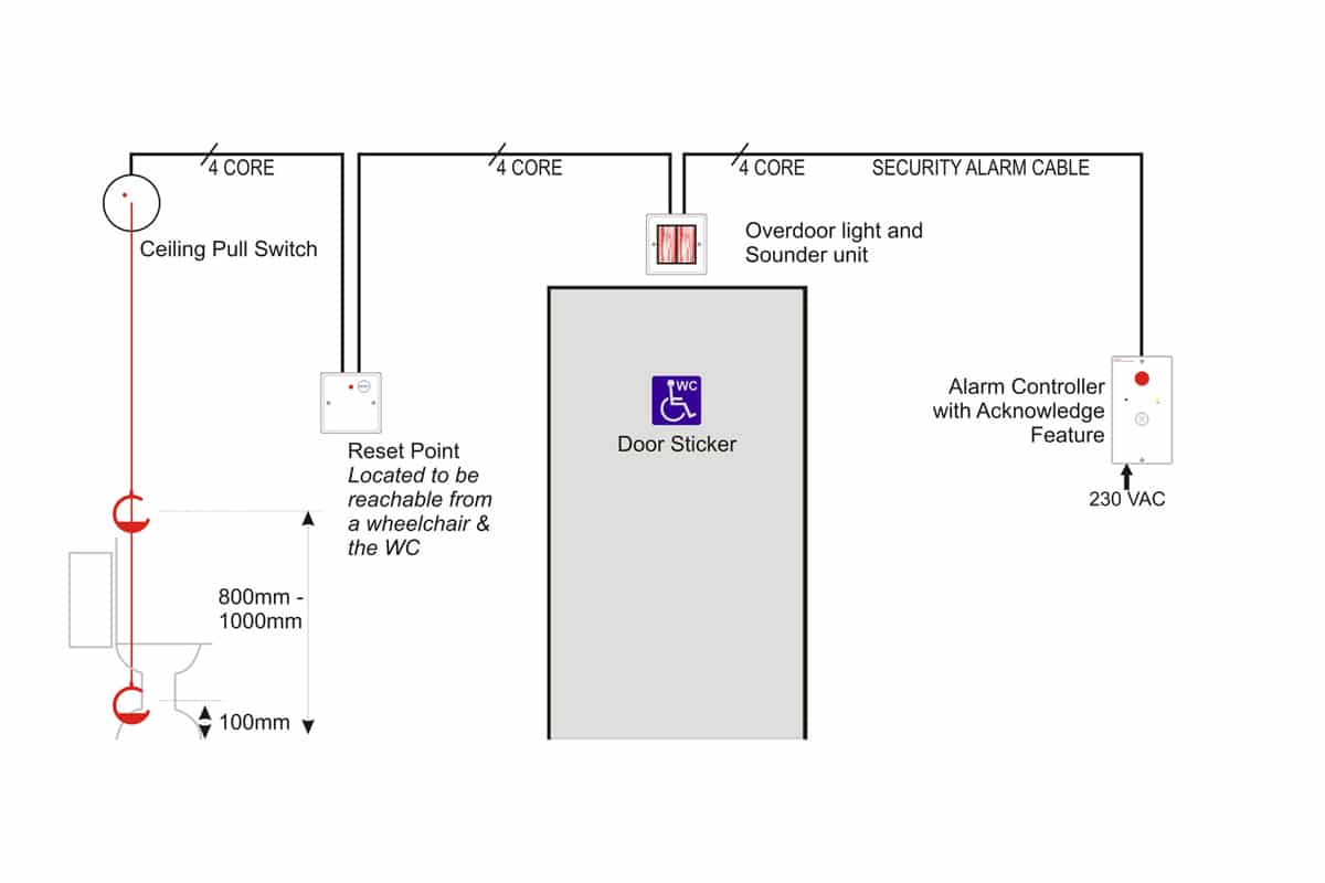
Key Components:
- Controller:
- Combined power supply and controller with a reset button, audible alarm, and large-diameter LED.
- Ceiling Pull Switch:
- Ceiling-mounted pull cord with a high-brightness LED, including two G-pulls set at different heights for accessibility.
- Reset Point:
- Reset button with LED to reset calls locally.
- Overdoor Light / Sounder:
- Triangular lens with an integral sounder to attract attention and indicate where help is required.
Features:
- Integral mains-powered PSU.
- Relay output option.
- BS8300:2009 acknowledge feature.
- Includes backup battery.
- Powerful LEDs and sounder.
- Supply healthy LED indicators.
- Reset button enable/disable option.
- Self-test facility.
- Twin G-pulls and LED.
- Reset point with reassurance LED.
- Overdoor light with sounder.
Installation Instructions:
- First Fix:
- Requires separate electrical back-boxes for the controller, overdoor light, and reset point.
- The ceiling pull switch is self-contained with its own surface mounting enclosure.
- Controller Mains Wiring:
- Must comply with current IEE Wiring Regulations or relevant national wiring regulations.
- Connection to the mains supply must be exclusive to this unit, using fixed wiring with 3 core PVC cable (min 0.75mm²), fed from an isolating switched fuse spur at 3 Amps.
- Low Voltage Wiring:
- Careful planning is required to segregate low-voltage wiring from mains wiring.
- Use a 4-core or 6-core security alarm cable (7/0.2 or similar).
- Mode Drill-Out Acknowledge (BS8300:2009):
- The controller reset button can act as an “Acknowledge” button to indicate assistance is on its way, with the acknowledged state lasting for 120 seconds.
- Reset Drill-Out:
- To ensure calls can only be reset within the WC area, the reset button on the controller may be disabled by gently twisting a 3mm drill bit on the circuit board.
- Self Test:
- Confirm the operation of all sounders and LED lights in the system by pressing the reset button on the controller twice in quick succession.
Operation:
- In standby mode, the controller ‘on’ LED is lit, and the sounder and LED are off.
- Activation of the ceiling pull switch triggers the controller’s audible sounder and LED, along with the overdoor light/sounder.
- Calls are reset at the reset point within the WC.
- Calls can be reset or acknowledged at the controller, with acknowledged calls returning after 120 seconds if not reset at the reset point.
Battery Life:
- The battery is continuously monitored; replace when the ‘on’ LED is dim or extinguished.
- Use only Alkaline Type A23 12volt battery, typically providing 24 hours standby.
System Expansion:
- Additional devices can be added, such as extra ceiling pulls or an additional overdoor light/sounder.
Important Note:
- The Disabled WC Alarm Kit does not include backboxes, fixings, cables, or tools.
This manual is essential for installers to ensure the proper setup and compliance of the Disabled WC Alarm Kit with BS8300:2009 standards, providing a reliable emergency assistance system for disabled WC installations.
File Type:
pdf
Categories:
Manual